[Controller Design] Day 1: Creating the Multibody System Using Simscape
Today marked the exciting beginning of our project on simulating multi-link mechanism control, a pivotal concept in dynamic systems and control theory. My objective for Day 1 was to construct the foundational multibody system using Simscape, which involved creating multi-link mechanism with varying numbers of links. The challenge here is not just about assembling a physical model, but also simulating how these systems behave under different conditions—a crucial aspect for anyone venturing into the world of advanced robotics and control systems.
I. A Multi-Link Mechanism with a Fixed Base
A. Overall System
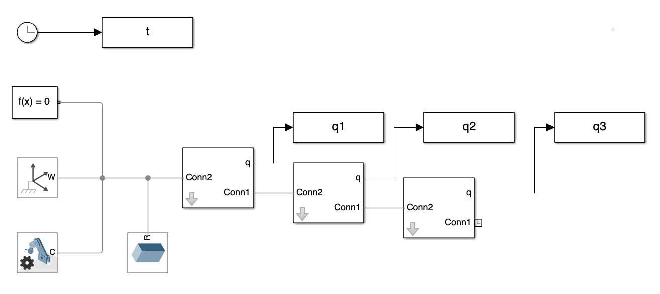
The process began with setting up the basic structure of the multi-link mechanism with a fixed base. We designed a schematic that includes components like the links and the fixed base that manage the multi-link mechanism’s movement (See Figure 1). This visual setup helps in understanding how each part interacts within the system and serves as a good starting point for simulation.
B. Subsystem - Link
Next, we focused on the Links, zooming into the subsystem that plays a critical role in the multi-link mechanism’s dynamics. The revolute joint determine how the multi-link mechanism reacts to forces and movements applied to it, which is essential for analyzing stability and control (See Figure 2). Understanding each component is vital for refining the simulation and ensuring accurate results.
In Figure 2, the subsystem of link 1 is depicted with several blocks.
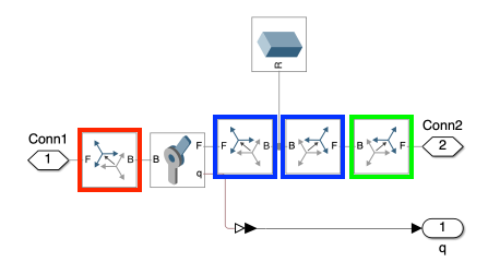
Each block is enclosed in a color-coded box to indicate its specific function:
-
Red Boxes: Blocks within the red boxes are crucial for adjusting the joint’s frame so that the joint’s rotational axis (default z-axis) aligns with the world frame’s y-axis.
-
Blue Boxes: Blocks within the blue boxes are used for linking the joints and the links together.
-
Green Box: The block in the green box is positioned at the end of the link. This setup is typically used for attaching additional components or for applying external forces to the system.
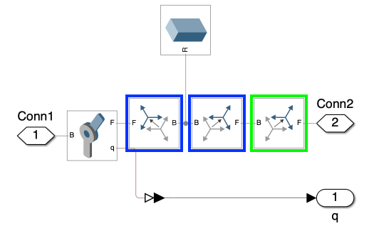
Similarly, Figure 3 illustrates the subsystem comprising links 2 and 3, depicted with several blocks. A rotational block is not required as the joint’s rotational axis is already aligned with the world frame’s y-axis.
By meticulously arranging these blocks and understanding their specific roles, we can create a versatile simulation environment that accurately mimics real-world physical conditions. This level of detail is imperative for developing effective control strategies and for the thorough analysis of the dynamics of multi-link mechanism.
C. Parameter Customization
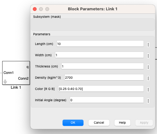
we utilized the mask editor in Simscape to enhance subsystem customization. This tool allowed us to encapsulate subsystems, thereby facilitating easy adjustments of parameters such as mass, length, and friction through a user-friendly interface. By clicking the “Edit” button, which is highlighted in a red box in Figure 4, we was able to add new parameters to the subsystems.
Figure 5 displays the interface after these additions. This makes much easier to modify the parameters without altering the core model structure.
D. Simulation Results
To solve the differential equation, we utilized the daessc solver, which is specifically designed for Simscape DAEs (Differential-Algebraic Equations), with variable step size.
Video 1 illustrates a non-chaotic motion resulting from a specific initial angle and link’s length. This setup reveals predictable and stable behavior, demonstrating how controlled conditions can ensure system stability.
Figure 6 provides a detailed analysis of the angular displacement for each joint of the triple multi-link mechanism with a fixed base under non-chaotic conditions. This illustrates how each joint behaves in terms of movement and speed when the system is stable and predictable.
Conversely, Video 2 captures the onset of chaotic behavior under a slightly altered set of conditions. A small change in the initial angle leads to unpredictable and complex dynamics. This showcases the system’s sensitive dependence on initial conditions—a defining characteristic of chaotic systems.
Figure 7 showcases the same parameter under chaotic conditions, highlighting the significant differences when small changes in initial conditions lead to complex and unpredictable dynamics. Comparing these images helps underline the critical impact of initial setup variations on the system’s behavior, offering valuable insights for designing mechanisms to control or utilize chaotic responses effectively.
II. A Multi-Link Mechanism with a Moving Base
A. Overall System
For the multi-link mechanism with a moving frame, we kept the links unchanged but made the base movable and added visualization along the x-axis.
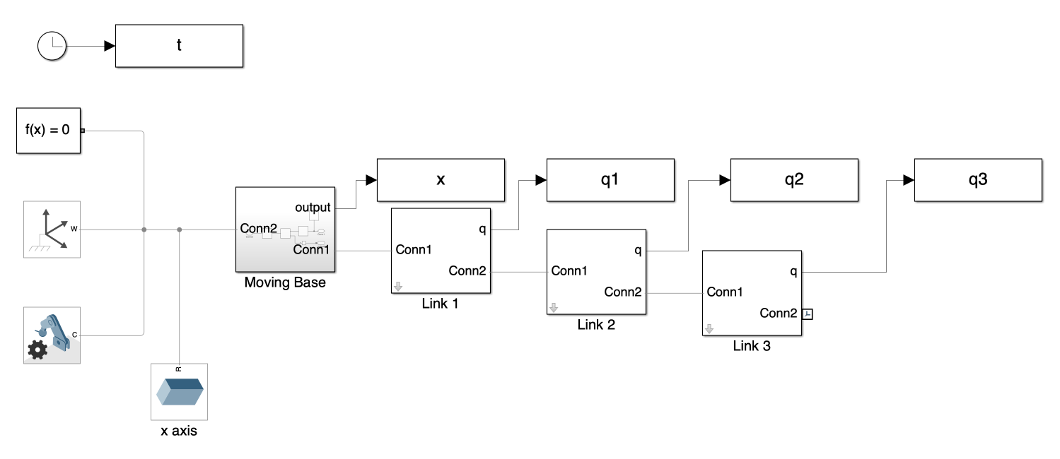
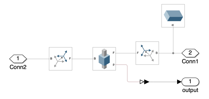
B. Subsystem - Moving Base
Figure 9 shows the moving base subsystem. Similar to the revolute joint, the translational axis of prismatic joints is the z-axis. Therefore, we need to rotate the joint’s frame to align the joint’s z-axis with the world frame’s x-axis.
C. Simulation Results
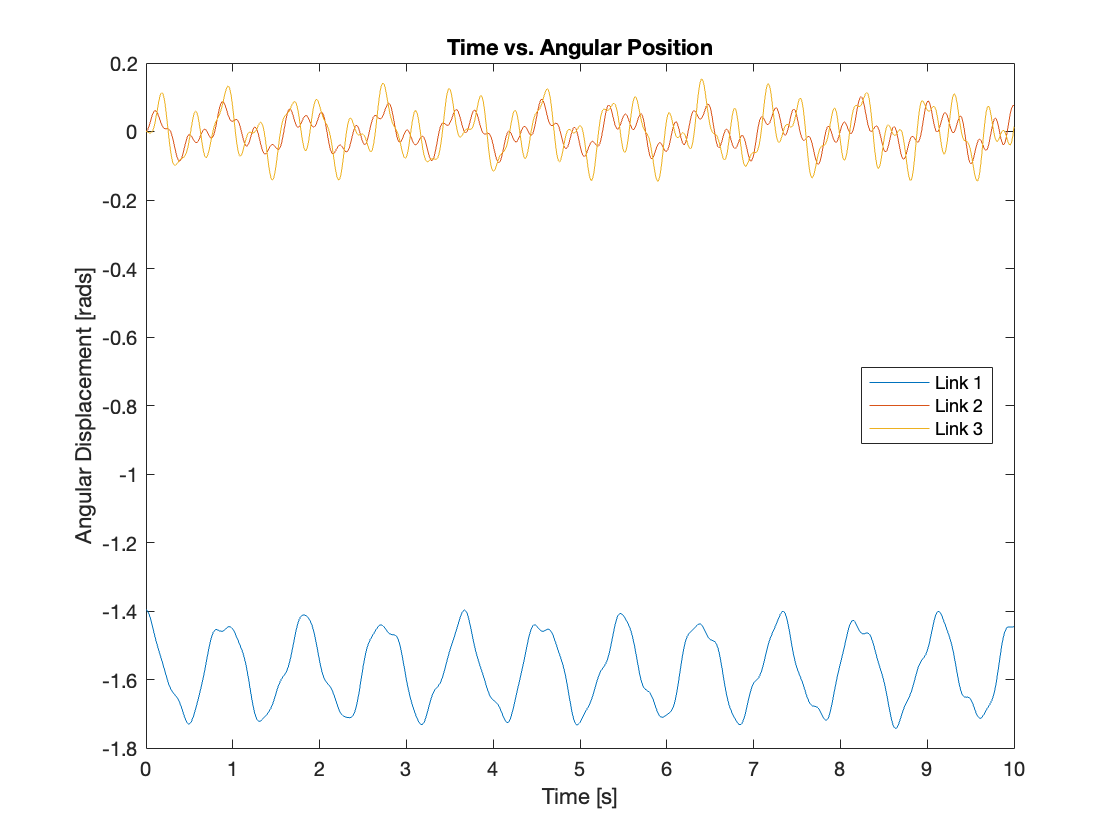
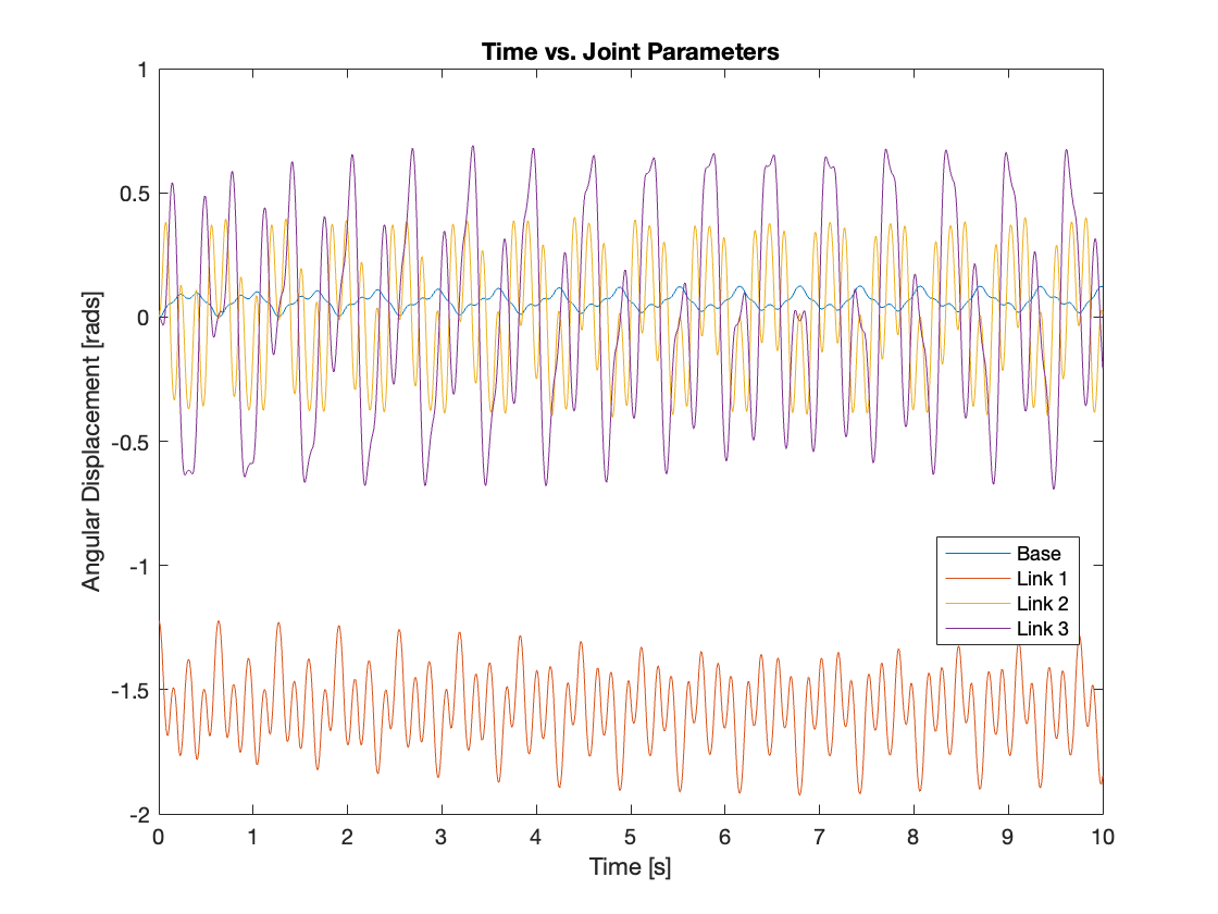
Video 3 depicts a non-chaotic motion resulting from a specific initial angle and link’s length, showing predictable behavior similar to systems with a fixed base, thus illustrating how controlled conditions can enhance system stability. Figure 10 captures the parameters of the base and each joint, providing a detailed view of the setup components.
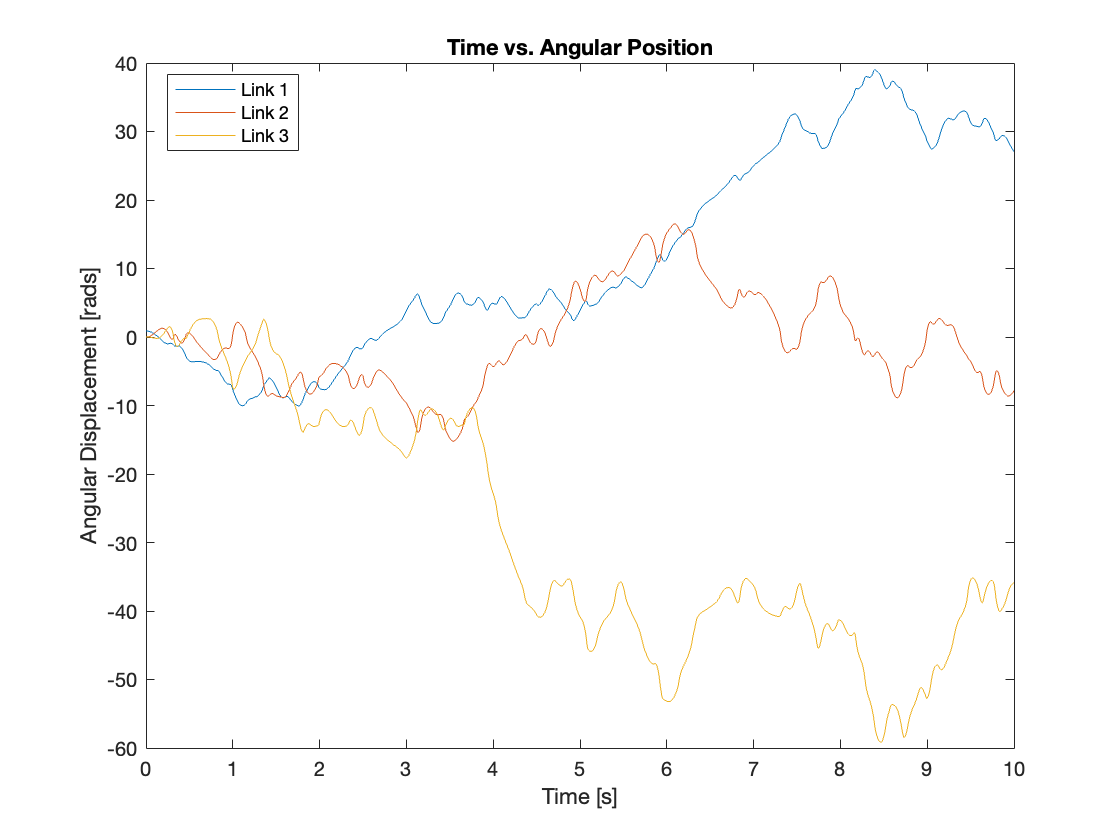
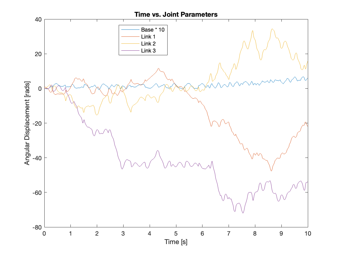
Conversely, Video 4 and Figure 11, akin to Video 2 and Figure 7, display the chaotic motion of a system with a moving base, along with the parameters of the base and each joint. The displacement of the base has been scaled up by a factor of 10 to enhance its visualization.
III. Conclusion
we chose different lengths for the multi-link mechanism primarily due to controllability concerns. Varying the lengths has helped in understanding how each variation impacts the system’s ability to be controlled, thus informing the development of more effective control strategies.
In the later post, we plan to delve deeper into the relationship between the length of each link and its controllability. This analysis is crucial as it will inform the implementation of a controllers for the multi-link mechanism. Understanding these relationships is key to developing effective control strategies that can manage the complexity and inherent challenges of chaotic systems.
It’s a blend of theory and practical application, and we’m eager to see where this journey takes us in the realm of control engineering. Stay tuned for more updates as we explore the fascinating world of multi-link mechanism and tackle the challenges of controlling chaotic systems!
You can find the Simulink model on my GitHub repository.
Enjoy Reading This Article?
Here are some more articles you might like to read next: